by Ved Vyas, Sanket H Deshpande & Tianze Guo
The lack of development of steam locomotives led to the demise of this good old technology. Instead of making improvements in the existing steam technology, engineers were more attracted towards its replacement by diesel or electric traction. However, with the help of the scientific advancements in the past, the steam industry can be revived today and operate at its full potential. A dedicated group of engineers, around the world, firmly believe that steam locomotives can indeed make a comeback and prove to be beneficial both economically and environmentally. In this section of the report, we are going to look at the factors that led to the replacement of steam locomotives in the early 20th century. We are then going to look at the new designs proposed by engineers which incorporate modern technology to improve these century-old locomotives for a better future.
Where We Left It and Where We Can Take It
There were indeed many problems – both economic and environmental – with the old steam locomotives. Analysing these problems and devising solutions will enable us to make efficient ‘modern’ steam locomotives that can compete with the diesel or electric locomotives of today.
From the economical point of view the old steam locomotives were not desirable because of high footplate staff costs, maintenance costs and high fuel consumption due to low thermal efficiencies and high carbon loss in the combustion process. Also high risk, stand-by losses and lack of inter-changeable parts made it obvious that these locomotives could not compete in the modern world.
In addition, environmental concerns such as excess smoke and heavy emission of NO2, CO2, SO2 plagued the steam locomotives as mentioned in the previous section.
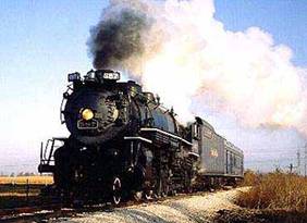
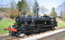
The image above describes a steam engine, as portrayed by the media: polluting (notice the black smoke) and suitable for carrying industrial goods only. However all this is to change with the introduction of the modern steam engines. Notice the clean burning of fuels in the modern steam engine below.
By making good use of modern technology we can build an efficient and clean steam engine. Features such as one man operation, minimum servicing requirements and short starting time are desirable from a modern steam engine. For the engine to be efficient it should not only provide high thermal efficiency but also be light weight. It should also provide clean and efficient combustion of fuel, good insulation and should incorporate interchangeable parts. Thus the steam engine can be more efficient and cause lesser pollution.
Now, let us look at how individual parts can be modified to give us a steam engine for the 21st century.
Fuel
There is a proposal of using extra light oil as a fuel for modern steam engines. Unlike heavy oil, light oil does not need to be preheated for use. Therefore heating coils can be eliminated from the design allowing the engine to be light weight and reduce energy consumption. New designs for burning light oil have to be developed because there are none present today. This adds to developments costs and coupled with the fact that oil reserves are depleting rapidly, the choice to use oil as a fuel in the 21st century is impractical. Oil combustion also adds pollutants such as CO2 to the atmosphere.
Another approach would be to use biomass as the fuel. The argument for biomass is that emitted CO2 would be reabsorbed by plants and it becomes a part of the carbon cycle, therefore, no ‘excess’ pollutants are added to the atmosphere. However, using biomass introduces complications to the whole system as it requires changing the firebox and boiler design. Only a few South American countries where “fuel plants” are largely available have actually made use of this technology.
A more realistic design proposes the use of low sulphur coal as the fuel. New steam engine can be designed with new combustion techniques, which can control the emission of pollutants below Environmental Protection agency (EPA) standards. Low cost and high abundance of coal make it the more appropriate fuel in the 21st century. Therefore in this report, we are going to explore the use of coal as a fuel in modern steam locomotives.
Firebox
In the design of a firebox, the main objective is to achieve maximum thermal efficiency. To produce enough heat to raise steam in the boiler more efficiently under the emission constraints, a new firebox with a new gas production technique is developed with 2 stages:
Stage 1:
Coal is mechanically distributed across the fuel bed, where it is burnt with little but sufficient air for complete combustion. This is meant to reduce char gasification; however, steam is injected into the furnace to produce more gases with the reduced air intake. Temperature of the burning coal is low in this manner; non combustible ashes (soot) would stay in the coal, where in the old steam locomotive it is discharged into environment. Moreover, the gas velocity is minimized ensuring fine particles of coal remain. This would greatly reduce the carbon losses; which in old engines could be over 50% at high speed.
Stage 2:
Remaining volatile and gaseous products are completely burnt with additional air in the fire box. The emission of harmful gases such as Sulphur oxides and nitrogen oxides are controlled to below EPA emission standards owing to the low temperature combustion technique. Ashes are agglomerated and collected safely instead of discharging it to atmosphere.
Boiler
Again, in order to achieve maximum efficiency, the boiler must be light weight and well insulated. To ensure sufficient water in the boiler, an electronic sensor can be used to maintain a safe water level. However, the sensor must account for various inclinations of the track.
According to a proposal for modern boilers water must be fed into the boiler using a feed pump. The feed pump must be belt driven, taking water from the source tanks. This water is then heated by passing it through the exhaust steam chamber and its entry into the boiler is regulated by a bypass valve. This valve can be automatically controlled using electronic sensors. Wet steam from the boiler is then superheated and is now ready to drive the locomotive.
Good insulation of the boiler is required as locomotives spend most of their time in the shed. Proper insulation of the boilers allows immediate start-up of the locomotive once it is out of the shed. Also by saving all the thermal energy, that would otherwise be lost, the insulation proves to be very cost effective. The development of boiler insulation faded away with the demise of steam locomotives. However, high quality insulation is in use for industrial boilers today and these insulating materials can be used for the modern steam engine.
Framework, Drive and Other Considerations
The overall framework has to be light weight and strong. This can be achieved by having an all-welded frame and using driving axles with hollow shafts. The locomotive suspensions must be of high quality for good shock-absorption and pulling heavy load efficiently. The tractive force must be applied directly to the wheels or through the shortest path possible, so as to avoid loss of energy. To avoid rolling-back, the hind truck must be equipped with a stabiliser.
Modern steam locomotives must be adaptable with the existing tracks so as to avoid costs of laying new tracks. This can be achieved, more or less, by varying the axle length. The height of the train above the track can be adjusted by changing the diameter of the wheels. Thus modern steam locomotives can be used on existing tracks – making them economically beneficial.
Our next concern is that of safety. Electronic sensors can be used in different parts of the train (as in the boiler) to ensure proper functioning of each part. Any error in any part must be reported to the driver on his display screen. Other safety features must be included in the design such as over-speed trip and roll-back protection.
Also, there must be different sets of synchronised brakes for the locomotive and the coaches. This will ensure safe stopping of the locomotive. To avoid wearing out of brakes, they must be of a high tensile strength and should be well lubricated. The heat produced in the braking process is then cooled using cold water producing steam. A silencer can be used to reduce the noise generated while braking.
It is worth noticing that apart from thermal energy, the modern locomotive will also utilise a fair amount of electrical energy using sensors, controllers and in the display screen of the driver. It is imperative, therefore, for the locomotive to carry a battery as a source of electrical energy. This battery must be kept separate from the steam generator – preferably at the rear of the locomotive. It can be charged mechanically while running using an alternator and using an external charger while in the shed.
Multiple Unit Capability
Multiple unit capability is the ability to use two or more engines connected together under the control of a single driver. This capability is highly desirable in steam locomotives as there is a limitation to the size and pulling capacity of a single engine. Effectively depending on the load required to be moved, more than one engine could be brought together and connected to work as one big locomotive. This sort of capability would make steam engines very competitive and would then be highly desirable for use on heavy duty main lines.
A computer control system would make this kind of multiple unit operation a reality. Attempts at implementing this kind of system were made by Wabco engineers in the1940’s. They designed and patented pneumatic and electro-pneumatic control systems for the multiple unit operations under a single driver (a pneumatic system is a system moved or worked by air pressure). With the ACE 3000 project this sort of idea was taken one step further where efforts were made to allow multiple unit operations with other steam engines and even diesel locomotives.
It becomes apparent that to be able to have multiple unit capability easily available, provisions must be made for single driver operation of locomotives. For this we must have power actuated locomotive controls, design of computer based interface for locomotive management, automatic control of the boiler systems and traction control.
Power Actuation
Operations such as braking safely, accelerating, steering, reversing had a completely mechanical operation in the traditional locomotives. To accelerate or decrease speed the driver invariably had to use huge levers which were mechanically directly connected to the locomotive. In modern engines this sort of operation must be done away with and computer or electrical control panels must be installed. For example when the driver initiates a command to brake on the control panel, actuators which relay his command will be powered and the brakes will be applied.
The Computer-Based Interface
The driver could have in front of him an interface module rather like a computer screen and also a control panel. This control panel would allow the driver to make instructions to the locomotive while the screen would be the source of feedback to driver regarding engine conditions. The onboard computer would also be used to maintain a database of the performance of the engine and the operating values for various critical components. This could be a source of knowledge, which after careful analysis could tell us how the locomotive could be better run, which components need repair or even how to make improvements to the design.
Traction Control
Inbuilt safety considerations could also be implemented through preinstalled commands for mode of action to be taken by the computer in certain situations. For example in case of braking, the onboard computer should manage the braking force so as to avoid locking the wheels. This would be similar to the anti-lock braking system in automobiles in use today.
Boiler Systems
The boiler system could process in real time the correct amount of fuel required to give the power demanded by the driver. The driver could increase the speed of the locomotive by using his control panel. The onboard computer would get the instructions from the driver and take action based on the operating conditions and also predetermined values to provide right amount of power increase. It would manage air supply to maintain efficient and complete combustion which would allow it to remain within environmentally safe limits.
Microprocessor control of basic operations such as fuel or air supply management and the development of power actuated locomotive controls would greatly help reduce the number of men required for operating the locomotive. As a result, one of the important targets in creating a modern locomotive would be to allow the driver of the locomotive to focus only on the steering of the locomotive rather than also have to be responsible for the efficiency and traction control of the engine. The design and implementation of modern computer controlled actuators and sensors could be used to make the job of the train driver much simpler.
British Efforts to Build a Modern Steam Engine
In efforts to design and build a modern steam locomotive, various attempts have been made around the world. One such commendable effort was by the A1 Trust. Their desire was to build a modern working model of the original A1 peppercorn design. This was the design made by Arthur Peppercorn, the last Chief Mechanical Engineer of the London and North Eastern Railway (LNER).
Originally there were 49 A1 locomotives operating on the East Coast Main Line in the post war period 1948/49. In a few cases the design of the A1 locomotives, incorporated roller bearings which meant that heavy maintenance was only required after an average of 118,000 miles. Also the design allowed it to run well even on low grade coal. The A1 were the cheapest locomotives to run compared to other locomotives that were already operating, but unfortunately, in the 1960’s there was a rapid move towards diesel engines. This meant that eventually by the end of 1966 all including the last surviving A1 601445 Saint Mungo had been scrapped.
In the 1990’s another group of railway enthusiasts came together with the intention of building an A1 peppercorn from scratch. This would become the largest single effort in railway preservation within Britain. There is certain affection towards the appearance and feel of the traditional locomotive, hence the idea remains that however modern the project might be, the overall look of the locomotive should be preserved for sentimental satisfaction. With this in mind, people like Ing. L.D. Porta also made some suggestion for design improvements to the A1 which would enormously increase its efficiency and performance.
The construction of this 50th A1 was undertaken at Darlington. The locomotive has been named the ‘Tornado’ and numbered 61063. A number of modifications have been planned for the Tornado A1 locomotive. The firebox will be completely made from welded steel. The original had a copper firebox which was riveted. The brake design for the locomotive has incorporated an air braking system as a result of considering the heavy operating conditions on the main line. A vacuum ejector will be fitted to accommodate use with all vacuum braked stock. The tender for the locomotive will be redesigned to eliminate water scoop and increase the capacity to 6000 gallons. Other design modifications suggested by Ing.L.D.Porta include changes to the inside cylinder arrangement, provisions for gas producer combustion system with enlarged combustion chamber, increased boiler pressure capacity. An advanced ‘Lemprex’ exhaust system would greatly help improve the design of the locomotive. Not all of the suggestions made by Porta were incorporated in the design of the Tornado. But all these changes undertaken ensure that the Tornado engine is thoroughly a modern incarnation of the original A1 design.
Another design for a modern steam engine was proposed by Dr. John Sharpe as a variation for the Beyer-Garratt. This would be a 4000 horsepower engine featuring 2-cylinder compound condensing units utilising a turbo re-compressor between two stages of expansion (see the figure below).
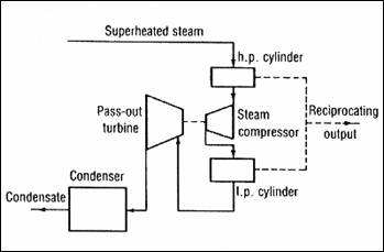
In this design, by adding a turbine-driven steam compressor feed back loop in between the high pressure (HP) and low pressure (LP) cylinder, exhausted steam from LP cylinder is fed into the Pass-out turbine to drive the steam compressor, which is used to increase the pressure of the steam from HP cylinder before fed into LP cylinder. This works similar to a turbo charger in use within many modern internal combustion engines to increase power and efficiency. This kind of engine would achieve a thermal efficiency of 15%.
Other Ideas for Modern Steam Engines from Around the World
In the United Sates, the National Steam Propulsion Company (NSPC) was formed in 1982 to reintroduce the coal fired steam locomotive back on to the railways of America. The main idea was the use of already existing diesel engine chassis to build the new steam engines. This method would make it easier for the railway to use existing facilities and maintenance operations without having to create too many new specialised processes. This would give the steam locomotive a bigger chance of success through being easily operable on the present railway. The locomotive would use a patented ‘Wormser Fluidised Combustion Boiler’ which would enable boiler pressure capacity in the range of 1000PSI. This boiler would allow the use of even low grade coal with high sulphur content to be burnt and still meet the environmental limits of the time. It was calculated that such a locomotive could give thermal efficiencies of approximately 18%. But with experience, time and more developments this thermal efficiency could be raised to around 27% in the later versions. The prototype of this kind of locomotive which was first made was called the CE-635 and was rated at 3500 horsepower. Effectively these engines would become desirable because they allowed higher savings on costs over their life-cycle as compared to the diesel while at the same reuse of chassis became a suitable way of recycling existing material.
